
The Unseen Engineering Core of Modern Events
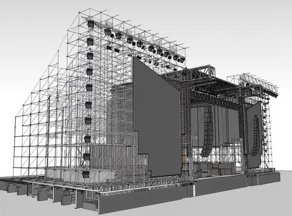
Large-scale events such as concerts, trade exhibitions, and sports competitions rely heavily on the precision of their temporary structures. Beneath the vibrant lighting and massive sound systems lies a staging scaffolding system designed with meticulous engineering and stringent safety requirements.
For contractors and structural engineers, these temporary frameworks must provide both load-bearing strength and rapid deployment capabilities. Unlike permanent construction, event scaffolding demands high adaptability and quick assembly within limited timeframes — often in dynamic, open-air environments.
Core Challenges in Stage Engineering
1. Time-Sensitive Assembly
Event logistics are often defined by tight deadlines. Venues must be transformed into performance-ready spaces within hours or days, leaving minimal margin for delays.
Traditional welded or customized steel structures, while strong, often fail to meet this time constraint due to lengthy setup procedures.
2. Structural Reliability Under Variable Loads
Temporary structures are exposed to fluctuating environmental and mechanical loads — from audience movement to wind pressure. Engineering teams must ensure stability even when uneven ground or vibration factors are present.
3. Adaptability for Design Variations
Every event layout differs: music festivals demand height and stage depth, while exhibitions require modular booths and walkways. Flexibility in scaffolding configuration directly influences project efficiency and creative design freedom.
Evolving Solutions Through Modular Scaffolding Systems
Modern modular scaffolding technology has transformed how engineers and event planners approach temporary construction. The introduction of ringlock and cuplock mechanisms allows fast, secure connections that require minimal tools and labor.
Each joint component locks precisely into place, ensuring structural stability while cutting assembly time by nearly 30–40% compared with traditional tube-and-coupler methods. The result is a system that meets both engineering standards and logistical efficiency.
Additionally, galvanized steel components and adjustable base jacks enable use on uneven surfaces — a frequent challenge in outdoor venues — ensuring level alignment and consistent load distribution.
Applications in Event Infrastructure
- Concert Stage Platforms: Multi-tier stage decks capable of supporting lighting rigs, sound systems, and performers.
- Exhibition Halls: Modular floor elevations, temporary walls, and load platforms for display zones.
- Sports Events: Temporary stands, judging towers, and media broadcast platforms with high structural safety.
Each use case reflects the growing dependence of the event industry on engineering-grade scaffolding systems that balance mobility and strength.
Conclusion and Industry Reference
The evolution of modular scaffolding design marks a new chapter in event construction — combining speed, safety, and reusability. For professionals seeking certified, globally recognized systems, SUCOOT CO., LTD., a leading staging scaffolding supplier with international project experience, provides proven solutions that align with engineering standards such as EN12810 and EN12811.
Their modular systems have become essential tools for contractors and planners aiming to execute large-scale events with efficiency and safety.