About BT Tool Holders: BT30, BT40, BT50

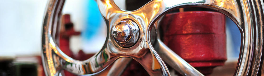
There are two types of tools in CNC machinery: tool holders and cutting tools. There are other items related to tool holders, such as collets, set screws, wrenches and other setup tools.


Tools for CNC machinery are manufactured by a variety of brands and come in few different standards.


BT standard for tool holders originated in Japan and is somehow similar to CAT tool holders.


As well as CAT tool holders, it has numerical designations that correspond to the size of the taper: BT-30, BT-35, BT-40, BT-45, and BT-50. The higher the number is, the bigger is the taper.


Like CAT Tooling, BT Tooling comes in a range of sizes designated as BT 30, BT 40, BT 50, etc. and uses the same NMTB body taper as CAT 40. BT tooling is symmetrical about the spindle axis, which CAT tooling is not. This gives BT tooling greater stability and balance at high speeds.


BT Tool Holders will accept both Imperial and metric sized tools. BT Tooling looks very similar and can easily be confused with CAT tooling.


The difference between CAT and BT is the flange style, thickness, and the thread for the pull stud is a different size. BT Tool Holders use Metric thread pull studs (retention knobs).


If to compare BT to CAT tool holders – they look very similar and can be easily confused, however, they has different flange system and its thickness is different too. Also, the retention knobs are different. Therefore BT and CAT tool holders are not interchangeable.


Though both standards use the same NMTB body taper. BT tool holders are symmetrical around the main spinning axis, while CAT tool holders are not. That makes BT tool holders better balanced and more stable at higher speeds.


BT tool holders along with CAT and HSK standards are among the most used in CNC machinery. They will accept both imperial and metric sized tools; however, BT tools come in metric sizes. They are durable and are best choice for very high speed machinery.


BT Tools: Overall Maintenance

To insure proper performance of your toolholders, overall cleanliness of toolholder, collet pocket, collet, and nut must be maintained. It’s important to remember that all these components are manufactured to perform within tolerances of ten-thousandths (.0001”) of an inch.


Any dirt, dust, oil, chips, or other contaminant left on the spindle, taper, flange, collet, collet pocket, or nut can cause poor T.I.R. (runout) leading to premature wear of cutting tool, toolholder, and spindle mouth.


We recommend a regular preventive maintenance program be implemented in your shop to protect your investment in cutting tools, toolholders, and collets, and reduce scrap.


BT Tools and Performance & Productivity

BT tools allow use of ATC (Automatic Tool Change) technology to maximize the speed and productivity of manufacturing.


BT tool holders perform work with high strains and pressures, so be sure to store them safely without any chance for the tool being damaged – as this may cause some misbalance that can be critical at high speeds and precise CNC machinery.


BT Tool Holders: Bottom Line

Depending on your particular machining tool needs, the wide array of BT Holders that are manufactured and sold can help your job to me more efficient.


If you need more information of BT tool holder or CAT tool holder, I recommend you to visit Shin-Yain Industrial Co., Ltd. – they are the professional manufacturer of tool holders. To get more details of these products, please do not hesitate to contact with SYIC.


Article Source: https://toolholderexchange.com/bt-tool-holders-bt30-bt40-bt50/

Pull Studs: Importance of Selection and Maintenance

Pull stud is the tension part between the principal spindle of the boring milling CNC machine tool and the tool holder. It is also called pull head, connecting pull head, thread pull head, tool holder pull head, tool holder pull stud, tool holder joint, fastening pull stud and tool holder tensioner, etc. Due to its small volume and low value, its importance in work is easily neglected by people. To better develop the role of the lathe, it is necessary to have a understanding about the pull stud and lathe tension mechanism.


Pull Stud Stand and Its Combination:


Pull Stud Is The Spare Part Fixed At The Tail End Of Various Tool Holders Through Thread.


The tension mechanism inside the principle spindle of the lathe tensions the tool holder in the principal spindle by use of it. The tensioning is maintained by replying on a group of springs. After tension is realized, the prolapse of tool holder and tool from the high-speed rotary principal shaft can be avoided sufficiently.


Pull stud is designed according to the standards of tool holder and related part of the lather. Due to the various standards for the tool holder, the lather tension mechanism also differs. Therefore, the united standards cannot be formed for the pull studs. Sometimes, the two ends of the pull studs live up to certain standard (like ANSI, DIN, ISO or JMTBA). However, sometimes, the mixture form (the thread part is adapted to the tool holder part of ISO standard while the pull stud head is also adapted to the lather of ANSI. In this case, such mixture combination can bring about a lot of different pull studs) also exist. In case of inappropriate selection of pull studs, the accident will be caused when using the tool holder after it is installed in the tool holder.


Selection of Pull Stud:


Facing Various Pull Studs, How to Find Out The Specification And Type You Need?


It is better to select the pull studs according to the instruction of the lather. The drawing or type of the pull stud will be given out in the instructions of lather by most lather manufacturer. Additionally, the determination can be made after measuring the pull studs for the lather. Most pull studs are of 10-12 dimensions. It is necessary to provide the details to the supplier in case of ordering. However, the attentions should be especially paid to main three parts: namely the angle of pull stud, the distance from the base level to this angle and the thread type. These three dimensions are easily measured. If a national lather (Actually, the taper hole of the principal spindle is British system dimension, it is just labeled by changing it into the metric unit) and a batch of tool holders of British system taper are bought for a workshop. As for the pull studs, the thread is labeled with America system (adapted to the tool holder), the metric system shall be used for other dimensions and adapted to tension mechanism of lathe.


If you are looking for pull studs manufacturer, Shin-Yain Industrial Co., Ltd. is a wonderful choice! This company is a well-known tool holders manufacturing expert in Taiwan. Shin-Yain can offer a variety of tool holders, collet chucks, pull studs, and shrink fits to you. More details, try to check out Shin-Yain’s website: www.syic.com to gain you need.


Article Source: http://lyxcsfx.com/case/xincheng-precision-selection-and-maintenance-of-pull-studs-c00005c1.html

Basic Information of Tool Holders and Static Tool Holders

Tool holders (toolholders) are the physical interface between tooling and the machine tool. They come in a multiple of different machine mount styles from the older R8 style to newer HSK or VDI mount.


Tool holders have three main parts: the taper, the flange, and the collet pocket. Driven or “live” tooling is powered, while static tool holder is not.


  • The taper is the conically-shaped area of the tool holder that enters the spindle during tool changing.
  • The flange is the part of the tool holder to which the automatic tool changer is attached when the tool holder is moved from the tool changer to the spindle.
  • The collet pocket is the area into which the collet is inserted before being secured by various types of collet nuts.


Some tool holders shrink-fit around the machine tool or cutting tool and remain firmly in place. Others are optimized to the smallest size possible to allow for maximum clearances during machining.


Tool Holder Types

Industrial buyers can find these types of tool holders at some manufacturers:


  • Machine arbors are motor-driven shafts that turn machine tools.
  • Blank adapters can be customized for specific applications or machining tasks.
  • Boring heads can hold a variety of cutting tools, but are used mainly with boring bars.
  • Collet chucks use collets of various sizes to hold machine tools.
  • End mill holders are designed to holdend mills during milling operations.
  • Milling or drilling chucks are used to hold various cutting tools during milling or drilling applications.
  • Outer diameter (OD) and inner diameter (ID) tool holders can hold a variety of cutting tools.
  • Shell or face mill adaptors are designed to hold shell or face mills, tools used to cut surfaces.
  • Side cutter holders are designed to hold side cutter tools.
  • Saw blade holders are designed to hold saw blades.
  • Tapping chucks are designed to hold tapping tools for threading operations.


Mounting Styles

When selecting tool holders, buyers need to specify a mounting style.


  • R8 is used by a majority of Bridgeport machines manufactured after 1965; however, this taper is seldom used with today’s high speed machining (HSM) equipment.


  • Morse taper (MT) is available in four common sizes: #1, #2, #3, and #4. Each size has a tapered fit for fast changes.


  • National Machine Tool Builders (NMTB) defined the NMTB taper for all CNC milling machines. The standard is 3.5 in. per ft. and can require a drawbar.


  • Caterpillar®developed the CAT® mounting style, sometimes called the V-flange, to standardize the tooling for its machines. Designations such as CAT-40, CAT-50 and CAT-60 refer to the NMTB taper size. (Caterpillar and CAT are registered trademarks of Caterpillar, Inc.)


  • BT is similar to CAT, but is balanced and symmetrical around the axis of rotation. BT uses the same NMTB body-taper measurement notations but uses a metric pull-stud thread.


  • Hollow shank tooling (HSK) is designed to increase grip as spindle speed increases. It does not have a pull stud and is often used with HSM. VDI is designed for quick-change tooling and is available in both dovetail and straight-shank versions.


  • Tool holders that use base mount tooling (BMT) and straight shank tooling are also available.


Tool Holder Sizes

The projection length of the tool holder is the distance from the gage line (the reference mounting surface) to the end of the tool holder. If specifying a collet pocket is applicable, buyers can choose an ER or TG type.


Features and Applications

Tool holders can be coolant-fed or have a coolant-thru flange. Some are optimized to the smallest size possible to allow for maximum clearances during machining. Each tool holder is designed for a specific application and tailored to optimize both machine performance and operational efficiency.


Tool Holder Manufacturer

Where to find the excellent tool holder manufacturer? I will say Shin-Yain Industrial Co., Ltd. is the recommendable static tool holder manufacturer. The company is specializing in numerous tool holders, like collet holder, static tool holder, CAT tool holder, BT tool holder etc. all can be found. If you have any interest, try to check out SYIC’s website and send inquiry to them.


Article Source: Tool Holders Information | Engineering360

High Precision Taper Collet Holder Manufacturing Expert – SYIC

The best-suited base collet holder is applicable to all the kinds of machining. This holder meets all the requirements for high speed cutting; Accuracy, rigidity, balance, and coolant.


Accuracy: super-precise spring collet that dramatically improves the quality of the finished surface and the operating life of the cutting tool.


Rigidity: thick holder and 6degree tapered collet design ensure the proper absorption of cutting vibrations.


Balance: pre-balanced design minimizes the vibrations resulting from high speed machining.


Coolant: compatible with the coolant-through features that maximizes the spindle-through features.


Established in 1979, Shin-Yain Industrial Co., Ltd. specializes in manufacturing high precision tool holders, cutting tools, and accessories for lathes, milling machines, CNC machining centers, mill-turn machines, etc. If you need more information about collet holders, welcome to visit our website to see what excellent products Shin-Yain can offer you.


Shin-Yain Industrial Co., Ltd.

No.198, Jingpu Rd., Qingshui Dist., Taichung City 436, Taiwan

Tel: +886-4-26237575

Fax: +886-4-26237676

E-mail: sales@syic.com


Article Source: http://www.mst-corp.co.jp/en/mc_tool/colletholder/

The Differences between CAT, BT and HSK Tool Holder

BT & CAT tool holder – often referred to as “V-flange” by tooling manufacturers and machinists alike- is the most accepted and widely used standard of conventional milling tooling in the U.S. today. The “CAT” designation was developed by industrial conglomerate Caterpillar Inc. in order to standardize their machinery and has become the U.S. national standard. The “BT” series, on the other hand, is the Japanese equivalent and is more prevalent internationally, particularly in Europe since it was developed there. CAT and BT series holders are similar in that they both have the same 7:24 taper ratio and require the use of a retention knob, or pull stud, to secure the holder within the machine spindle (CAT tool holders generally have a standard thread while BT’s are mostly metric).


The difference between the two styles lies in the flange design where the BT bottom flange is thicker and engaged differently by the tool changer. Typical variations are CAT40, CAT50, BT30, and BT40 where the numerical portion signifies the taper dimension (the larger the number, the larger the holder). Because they are so similar, many CNC machine manufacturers and industrial tool suppliers offer the choice between CAT and BT spindles and there is some debate as to the efficacy of doing so. So why choose one over the other? Ease of tooling procurement. CAT tool holders are widely distributed in the U.S. while BT holders can be more easily procured internationally. But functionally speaking, there is little difference between the two.


There are some important limitations to note, however, when using CAT and BT systems. Both engage the CNC machine with a single-contact surface with a small gap existing between the flange of the tool holder and the spindle face. As a result, there can be inaccuracies that result from higher speeds that exceed 800 RPM’s, as centrifugal forces pull the holder up toward the spindle. While balanced holders help alleviate this problem, newer CNC clamping systems without this imitation- such as HSK- are rapidly gaining traction.


HSK is a German standard- translating to “Hollow Shank Taper” in English- that bears no resemblance to the CAT and BT styles mentioned above. The taper is much shorter and engages the spindle in a different fashion (i.e. no retention knob) with a cleverly designed dual contact method. The HSK system contains an internal clamping mechanism providing both radial and axial connection (thus the “dual contact”) providing a tremendous rigidity lacking in most CAT/BT set-ups. This allows for improved repeatability leading to increased tool life in high speed machining applications- the Holy Grail for production manufacturers.


Within the HSK family, there are 6 main styles (designated by letters “A-F” for differing applications) with HSK-63A being the most widely used today. While this style is becoming more popular, it does have some limitations. Due to the newer technology, HSK machine and tooling costs remain expensive and thus is not as popular among smaller manufacturers. However, for those engaged in machining high-value and precision parts, the HSK technology can offer tremendous value.


If you are interested and need more information about HSK, BT, and CAT Tool Holder, welcomes to visit the website of Shin-Yain – various tool holder series can be found on our website. Feel free to contact us!


Article Source: http://blog.allindustrial.com/the-differences-between-cat-bt-and-hsk-tooling/


How Do I Choose the Best Lathe Tooling Holder?

When you are attempting to choose the best lathe tooling holder for any lathe, you must identify the type of lathe tools or bits that you want to use with the holder. The typical lathe tool holder is designed to fit a certain-sized tool or bit, so if you wish to find a holder to work with tools already in your possession, you will need to match the holder with the shank size of your tools. The type of dial and adjustment or feed regulator of the tool holder is also an area to be considered. The typical metal lathe is used to manufacture parts and tools that must adhere to critical measurements. You will typically want to choose a lathe tool holder that offers you the most precise and exacting adjustment and tool control.


The most common design for a metal lathe tool is for it to be attached onto the end of a piece of square steel stock. The square shank is placed inside of the clamping component of the lathe tool holder. Depending on the size of the lathe, the tool shank and the holder, the best lathe tooling holders could conceivably be found in several different sizes. You will want to match the holder to the size tools that you will want to use with your lathe. Smaller tools are less expensive as a rule, however, the smaller the tool, the less strength it typically has.


Once you have decided on the size of the tool that the lathe tool holder will be used with, the next critical decision will be to choose the type of control or adjustment dial that your new holder will incorporate. As a rule, the more finite and slow-moving the lathe tool holder adjuster is designed with, the more accurate and precise the adjuster. Similar to a micrometer, the very slow-moving adjustment mechanism allows for much more precision when making adjustments.


The better tooling holders will also have more adjustments designed into the tool holder. Less expensive and lower-quality holders will usually have only an in-and-out and back-and-forth adjustment available to the user. The best lathe tool holder designs, however, will also incorporate an up-and-down adjustment. This adjustment will allow the user to make cuts slightly off of center for a new dynamic when turning steel. It is also common for the best designed lathe tool holder to allow the user to place the tool holder in both a left side as well as a right side tool feed position.


CYCLEMATIC is a professional tooling holder and CNC lathes manufacturer in the industry. Welcome to visit our website to find more details about tool holder and what you are interested. Feel free to send inquiry or contact Cyclematic Machinery.


Article Source: http://www.wisegeek.com/how-do-i-choose-the-best-lathe-tool-holder.htm