About BT Tool Holders: BT30, BT40, BT50

There are two types of tools in CNC machinery: tool holders and cutting tools. There are other items related to tool holders, such as collets, set screws, wrenches and other setup tools.


Tools for CNC machinery are manufactured by a variety of brands and come in few different standards.


BT standard for tool holders originated in Japan and is somehow similar to CAT tool holders.


As well as CAT tool holders, it has numerical designations that correspond to the size of the taper: BT-30, BT-35, BT-40, BT-45, and BT-50. The higher the number is, the bigger is the taper.


Like CAT Tooling, BT Tooling comes in a range of sizes designated as BT 30, BT 40, BT 50, etc. and uses the same NMTB body taper as CAT 40. BT tooling is symmetrical about the spindle axis, which CAT tooling is not. This gives BT tooling greater stability and balance at high speeds.


BT Tool Holders will accept both Imperial and metric sized tools. BT Tooling looks very similar and can easily be confused with CAT tooling.


The difference between CAT and BT is the flange style, thickness, and the thread for the pull stud is a different size. BT Tool Holders use Metric thread pull studs (retention knobs).


If to compare BT to CAT tool holders – they look very similar and can be easily confused, however, they has different flange system and its thickness is different too. Also, the retention knobs are different. Therefore BT and CAT tool holders are not interchangeable.


Though both standards use the same NMTB body taper. BT tool holders are symmetrical around the main spinning axis, while CAT tool holders are not. That makes BT tool holders better balanced and more stable at higher speeds.


BT tool holders along with CAT and HSK standards are among the most used in CNC machinery. They will accept both imperial and metric sized tools; however, BT tools come in metric sizes. They are durable and are best choice for very high speed machinery.


BT Tools: Overall Maintenance

To insure proper performance of your toolholders, overall cleanliness of toolholder, collet pocket, collet, and nut must be maintained. It’s important to remember that all these components are manufactured to perform within tolerances of ten-thousandths (.0001”) of an inch.


Any dirt, dust, oil, chips, or other contaminant left on the spindle, taper, flange, collet, collet pocket, or nut can cause poor T.I.R. (runout) leading to premature wear of cutting tool, toolholder, and spindle mouth.


We recommend a regular preventive maintenance program be implemented in your shop to protect your investment in cutting tools, toolholders, and collets, and reduce scrap.


BT Tools and Performance & Productivity

BT tools allow use of ATC (Automatic Tool Change) technology to maximize the speed and productivity of manufacturing.


BT tool holders perform work with high strains and pressures, so be sure to store them safely without any chance for the tool being damaged – as this may cause some misbalance that can be critical at high speeds and precise CNC machinery.


BT Tool Holders: Bottom Line

Depending on your particular machining tool needs, the wide array of BT Holders that are manufactured and sold can help your job to me more efficient.


If you need more information of BT tool holder or CAT tool holder, I recommend you to visit Shin-Yain Industrial Co., Ltd. – they are the professional manufacturer of tool holders. To get more details of these products, please do not hesitate to contact with SYIC.


Article Source: https://toolholderexchange.com/bt-tool-holders-bt30-bt40-bt50/

Vacuum Forming Plastic Process: The Economical Way for Manufacturing Plastic Parts

Vacuum forming is a very economical method for producing plastic parts. The vacuum forming plastic process can produce parts in various configurations in small and large quantities at a reasonable price. This process involves the controlled heating of plastic materials to a temperature where it is flexible enough to be altered by the shape of a mold with the help of vacuum. In this method, the heated plastic sheet is forced against the mold by the air pressure differential created by pulling a vacuum between the sheet and the mold.


Vacuum Forming Can Be Used For Projects Like:

  • Product packaging
  • Agricultural applications
  • Medical applications
  • Lift truck enclosures
  • Railcar interior trim parts and seating components
  • Engine covers for construction equipment
  • Fascias for outdoor kiosks and ATM applications


Vacuum forming has advantages over other plastic production methods.


Here Are Some Potential Advantages That Would Make Vacuum Forming A Good Choice For Your Plastic Part:

  • Large parts or multi-part uses
  • Moderate annual volumes
  • Tight tooling budget
  • Rapid product development


Materials Commonly Used In Vacuum Forming:

  • ABS
  • PC / ABS
  • HDPE
  • TPO
  • HIPS
  • PVC / Acrylic

If you need vacuum forming services, I sincerely recommend you to contact with Marathon Enterprise Co., Ltd. – they are Taiwan professional vacuum forming plastic packaging supplier. You can get services of providing PP sheets, LDPE sheets, transparent plastic sheet, PP food container, etc. To get more details, please do not hesitate to contact Marathon at +886-3-3590801.


Article Source: https://www.emcoplastics.com/vacuum-forming/

Victor Taichung Sees 70% of Orders for Customized Machine Tools

Taiwan-based machine maker Victor Taichung Machinery Works has coped with waning competitiveness in prices for the export markets by offering customized manufacturing services to create product differentiation, with around 70% of orders associated with customization, according to company chairman MH Huang.


Huang said that Taiwan machine tool makers used to see their quotes some 30-40% lower than those offered by their biggest competitors from Japan, but such a price competitiveness has been significantly undermined by the sharp depreciation of the Japanese yen. As a result, international customers have turned to Japan machine tool brands, directly squeezing the survival space for Taiwan makers.


Huang said that since 2013, Victor Taichung has maintained a customer value-creating application center, gathering the firm’s experienced sales staff and engineers to directly face customers and respond to their actual needs. This way, Victor Taichung can agilely adjust its product development strategies based on direct responses from customers, thus effectively boosting product values and customer loyalty through customized production services.


Huang stressed that Taiwan machine tool makers cannot compete well with China and Korea rivals in terms of production volume of low- to medium-tier models or with Japan makers in the market for high-end products. Accordingly, he indicated, it will be a major challenge for business transformation of Taiwan machine tool builders as to how they can work out differentiation to highlight corporate values and even develop the market for higher-end products.


If you have any interest in vertical machining centers and much more custom machine tools, come and visit Victor Taichung Machinery Works Co., Ltd. for more details!


Article Source: https://www.twmt.tw/victor-taichung-sees-70-of-orders-for-customized-machine-tools/

The Difference Between Proportional vs. Directional vs. Servo Valves

Understanding the available technologies in fluid power is imperative in order to design the most efficient, cost effective, and energy saving system. Traditional hydraulic equipment designs used directional control valves almost exclusively.


These directional valves are sometimes referred to as either “switching” or “bang-bang” valves and can be used to control flow direction, flow volume and fluid pressure. These valves can be operated by either AC or DC power.


Directional Control Valves


Directional control valves have been commonly referred to as switching valves because they simply direct or “switch” fluid passing through the valve from the source of flow to one of a selection of available cylinder ports. The flow control variety of valve generally selects an orifice which only allows a specified volume of flow to pass. The specified volume controls the speed of a cylinder or hydraulic motor. Likewise, the pressure control type is used to select a particular pressure setting.


Changing direction, flow or pressure during machine operation with these valves would require a separate individual valve for each direction, flow or pressure desired. The hydraulic circuit would become quite complex very quickly!


Proportional Valves


The technological solution to these more complex circuits has been the development of proportional valves. These revolutionary valves allow infinite positioning of spools, thus providing infinitely adjustable flow volumes. Either stroke-controlled or force-controlled solenoids are used to achieve the infinite positioning of spools.


This variable positioning allows spools to be designed with metering notches to provide flow/speed control as well as directional control functions all in one valve, instead of requiring separate valves for direction and speed. The other major benefit is when the circuit requires more than one speed. The various speeds are achieved by changing the electrical signal level to deliver the flow/speed required. No additional hydraulic components are required! These proportional directional valves are controlled by DC power.


The proportional controls, used with their associated electronic controls, also add the desirable features of acceleration and deceleration. This offers a variety of machine cycles, safely operated at greater speeds, yet with controlled start and stop characteristics. Regulated acceleration and deceleration result in improved machine overall cycle times and production rates.


Servo Valves


The third type of hydraulic directional control technology is the servo valve. Servo valves are not a new technology as servo valves were first used in the 1940s. Servo valves operate with very high accuracy, very high repeatability, very low hysteresis, and very high frequency response. Servo valves are used in conjunction with more sophisticated electronics and closed loop systems. As a result, servo valves are always much more expensive. A proportional control valve system can be used to improve control of most machines without the high price tag of servo control systems.


If you need more information of directional control valves or other hydraulic control valves, I recommend you to visit Propiston Hydraulics Co., Ltd. – they are the professional manufacturer of piston pumps and flow control valves. To get more details, welcome to check out their website and feel free to contact with Propiston Hydraulics!


Article Source: https://www.qualityhydraulics.com/blog/what-proportional-valve/

Types of Transmission Oil Seals: Static and Dynamic

There are two main types of oil seal: static and dynamic. A static oil seal fits between two non-moving parts, a dynamic oil seal between a stationary part and a moving one. Most oil seals are made of synthetic rubber.


An example of a static seal is a simple ‘O’ ring. These seals can be found in such places as the oil filter used on combined automatic gearbox and engine units, on conventional gearbox front covers and in automatic gearboxes.


Dynamic seals are more complex in shape, with one or two lips, depending on where they are situated. These transmission oil seals are widely used in the transmission system of both front and rear-wheel-drive cars, where oil must be sealed in where a rotating shaft passes through a component. For example, at the outer end of a half shaft and on the differential pinion.


Types of Oil Seals

Dynamic seals also contain a thin coiled spring, called a ‘garter spring’, which holds the sealing lip in contact with the revolving shaft.


Many seals have a metal outer casing for added strength and ease of fitting. Because the seal is in constant contact with a moving part, dynamic seals eventually wear and begin to leak, and both dynamic and static seals deteriorate with age.


Most seals are inexpensive and easy to replace, but many are in places where you must do a lot of dismantling to get at them.


For example, gearbox oil seals (apart from the extension-housing seal on rear-wheel-drive cars) can be replaced only with the gearbox removed – a task best left to a garage.


However, the seals on the rear axle and final drive should all be possible to replace fairly easily, although special tools may be necessary.


After many miles and several new seals, the moving part against which the dynamic seal fits may wear.


Slight wear can sometimes be taken up by fitting a shim between the seal and its housing, to change the point of contact. But if a shaft becomes seriously grooved it must be replaced or repaired at a garage or engineering machine shop.


This is not a common occurrence, but any point at which a shaft rotates in a seal is a possible leak source. Check such points regularly.


When fitting and handling any oil seal, keep it and its sealing point absolutely free from dirt and grit. Make sure you fit the seal the right way round. The lip (or lips) always faces the oil it is sealing.


To get more information of transmission oil seals, I sincerely recommend you to visit ASA Oil Seals Co., Ltd. – they are the professional oil seal manufacturer in the industry. If you need much more choice of oil seals, please contact with ASA immediately!


Article Source: https://www.howacarworks.com/transmission/replacing-transmission-oil-seals

Do You Know What BTA Drilling Is?

What is BTA Drilling?

Start Here: Deep Hole Drilling Overview

BTA drilling is a deep hole drilling process that uses a specialized drilling tool on a long drill tube to produce deep holes in metal, from holes with a diameter of 20 mm [0.80 in] and larger, up to depth-to-diameter ratios of 400:1. BTA drilling is the most effective method of drilling deep holes, as it is a cleaner, more reliable and capable process than conventional twist drills, and can achieve larger diameters and higher feed rates than the alternative gundrilling.


BTA drilling tool heads are threaded or mounted onto long drill tubes, and use multiple cutting surfaces on a single tool to remove chips efficiently, exhausting them using high-pressure coolant through holes in the tool head, then out the drill tube and through the machining spindle. BTA tooling is available in brazed or inserted carbide configurations.


BTA stands for Boring and Trepanning Association, and is also sometimes referred to as STS (single tube system) drilling, as it uses one single drill tube for the BTA tool, compared to other processes such as ejector drilling, which use two.


BTA Drilling vs Gun Drilling

BTA drilling can achieve drill feed rates of typically 5-7 times faster than gundrilling at the same diameter, due to the tool design, more efficient chip exhaust, and machine design and power. BTA drilling machines introduce coolant around the tool head, and evacuate chips through the drill and machine spindle, compared to gundrilling, where coolant is introduced internally and chips exit through an external groove. BTA drilling is effective in holes from 20 – 200 mm [0.80 – 8.00 in], a greater size range than gundrilling.


Optimal Specifications for BTA Drilling

BTA deep hole drilling is the ideal process for a range of larger deep hole drilled depths and diameters. BTA drilling, and secondary processes, are capable of drilling extreme depth-to-diameter ratio holes while achieving strict tolerances.


BTA Tooling Diameter Range

  • 8 – 65 mm Brazed Disposable BTA
  • 10 – 114 mm Spade Drill BTA
  • 16 – 28 mm Indexable BTA, Single Insert
  • 25 mm +     Indexable BTA, Multiple Insert


BTA Drilling Equipment

Deep hole drilling machines that are designed to perform BTA and related processes are complex systems of high-precision components, designed and built for extremely deep holes and strict tolerances.


If you need more information of BTA drilling equipment, I sincerely recommend you to visit Honge Precision Industries Corp. – they can provide high-quality and high-performance BTA deep hole drilling machine for clients. To get more details of this hole drilling machine, welcome to check out their website and feel free to contact with Honge Precision Industries!


Article Source: https://www.unisig.com/information-and-resources/what-is-deep-hole-drilling/what-is-bta-drilling/

Central Impression Press Buyer’s Guide: Productivity vs. Cost Concerns

Maximum productivity at minimum cost! Mid web and wide web flexographers want it all from any new press that gets installed in their plants. High on their lists of demands: quick-change features, waste management assets, open access to print decks and all componentry they hold. “Compact and capable” is the mantra. The mission: control, control, control.


Another three Cs—“connectivity, customization and color”—are carefully evaluated in pursuit of peak performance. Energy efficiency is seen as desirable; ease of materials handling, attractive. Automated features are built into the design and are directly linked to press uptime, quality output and customer satisfaction. They impact registration, impression, tension, washup, temperature control, defect detection, etc.


Recognizing flexography as a highly sensitive process, today’s converters pride themselves on efficiency and versatility and they expect the same from their presses. They calibrate or fingerprint machinery, yet stand ready to adapt at a moment’s notice and compensate for every variable that arises.


Business partners are acutely familiar with these printers’ daily challenges and tribulations. Engineers dedicate hour after hour to addressing new needs as they are identified. FLEXO Magazine set out to learn more about those evolving needs, so the magazine recently approached representatives from major original equipment manufacturer (OEM) and asked list out 10 features should consider when evaluating the purchase of a mid-web or wide web central impression press.


Quality Control

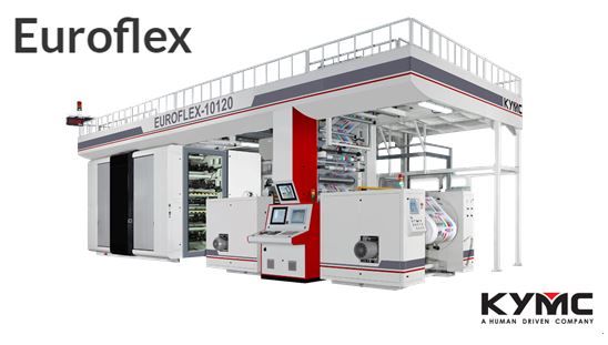
Setup and breakdown of every job is the key to saving both time and money. Standard features are now driving quality control and resulting in noticeable continuous improvement. That’s the position held by John Pan, general manager, Kuen Yuh Machinery Engineering Co., Ltd. (KYMC). He contends that, “Automation is boosting productivity.”


John uses that word in listing out 50 percent of the top 10 concerns to address in evaluating a potential press purchase.

KYMC Euroflex CI Flexo Press

  • Auto-Register Control—a good and effective automatic pre-register control system can set all colors in register within 164-ft. (50-m.), as on an 8-color press
  • Auto-Impression Control—good and effective auto-impression control should be able to set the impression for all colors within 656-ft. (200-m.), as on an 8-color press. Most importantly, it can set the desired impression from the operator’s determination, not the machine’s
  • Auto Wash With Auto Ink Viscosity And Temperature Control—keeping ink under control is the key for quality print, therefore, ink viscosity and temperature control are equally important to the auto-wash system
  • Drum Cleaner—the drum cleaner really saves the operator a great amount of time and is an important issue for quality print production
  • Auto Defect Detection—100 percent full width defect detection certainly benefits uninterrupted quality control. It increases productivity through automatic print monitoring, reduces waste and complaints, and increases customer satisfaction
  • Print and Anilox Sleeve System—the sleeve system is becoming standard on every modern press, yet customers should pay attention to the type of sleeve they are acquiring. It will affect the quality of printing and the life of the sleeve
  • Auto Splice on Unwind and Rewind, And Reel Handling System—continuous running while orchestrating a reel change has become a challenge to the operator. He or she needs a system to help to load/unload the reel every 20 to 30 minutes easy and efficiently. Those systems include a trolley, lifting table, robot, etc.
  • Energy Saving Drying System—a high-efficiency drying system is required on a high-speed press, yet it needs to be energy saving as well. Heat recovery and/or the use of an energy saving heating element/source are becoming standard on every modern press
  • Hybrid Solution—thanks to the development of the electronic driving system, the link of post processes (finishing) on the press is no longer an issue. This includes: inline coating/lamination, inline digital printing, inline cutting/sheeting, inline bag making, etc.
  • Ready for Industry 4.0—the CI flexo press must demonstrate interconnectivity, with major components monitored through any mobile device. It must also be able to connect to external management systems like APS, MES and ERP


John predicts the industrial production revolution will continue. “All printers should prepare themselves. The most basic principle in the new industrial revolution is that their equipment has the ability to connect with other equipment or systems through the network.”


Standing in Unison

Fast-change, quick-set, operator-friendly, quality-minded machinery is what every OEM FLEXO talked to says converters expect of their flexo press. Material-minded and considerably equipped with automated features is translating to faster, cheaper, better, more efficient print production.


The advent, arrival and acceptance of the integrated and optimized press is driving the principle of “control without compromise” with continuous improvement evident with each passing year.


Article Source: Flexographic Technical Association

Do You Know What Film Capacitors Are?

Film capacitors are capacitors which use a thin plastic film as the dielectric. This film is made extremely thin using a sophisticated film drawing process. Once the film is manufactured, it may be metallized or left untreated, depending on the needed properties of the capacitor. Electrodes are then added and the assembly is mounted into a case which protects it from environmental factors. They are used in many applications because of their stability, low inductance and low cost. There are many types of film capacitors, including polyester film, metallized film, polypropylene film, PTFE film and polystyrene film. The core difference between these capacitor types is the material used as the dielectric, and the proper dielectric must be chosen according to the application.


PTFE film capacitors, for example, are heat-resistant and used in aerospace and military technology, while metallized polyester film capacitors are used in applications that require long term stability at a relatively low. Cheaper plastics are used if cost is a bigger concern than performance.


Film Capacitor Definition

A film capacitor is a capacitor that uses a thin plastic film as the dielectric. They are relatively cheap, stable over time and have low self-inductance and ESR, while some film capacitors can withstand large reactive power values.


Characteristics

Film capacitors are widely used because of their superior characteristics. This capacitor type is not polarized, which makes them suitable for AC signal and power use. Film capacitors can be made with very high precision capacitance values, and they retain that value longer than other capacitor types. This means that the aging process is generally slower than in other capacitor types, such as the electrolytic capacitor.


Film capacitors have a long shelf and service life, and are very reliable, with a very low average failure rate. They have low ESR (Equivalent Series Resistance), low self-inductance (ESL), and as a result very low dissipation factors. They can be made to withstand voltages in the kilovolt range and can provide very high surge current pulses. A special class of film capacitors, which is called power film capacitors, is available, and this class of film capacitors can withstand reactive power in excess of 200 volt-amperes. These capacitors may have special screw-type terminals which can withstand high currents. Screw-type terminals replace soldered joints because power film capacitors sometimes need to be changed in the field.


Unfortunately, their superior electrical properties and stability come at a price. Film capacitors are bulkier than their electrolytic equivalents, which mean that limited SMT (Surface – Mount Technology) packages are available. They can also burst into flames if overloaded, but this characteristic is somewhat common among different capacitor types.


Construction and Properties

Film capacitors are made of a thin dielectric film which may or may not be metallized on one side. The film is extremely thin, with the thickness being under 1 µm. After the film is drawn to the desired thickness, the film is cut into ribbons. The width of the ribbons depends on the capacity of the capacitor being produced. Two ribbons of film are wound together into a roll, which is often pressed into an oval shape so that it can fit into a rectangular case. This is important because rectangular components save precious space on the printed circuit board. Electrodes are added by connecting each of the two electrodes to one of the films. A voltage is applied to burn out any imperfections using the self-healing property of film capacitors. The case is then sealed using silicon oil to protect the film roll against moisture, and dipped in plastic to hermetically seal the interior.


Typical film capacitors have capacitances ranging from below 1nF to 30µF. They can be made in voltage ratings as low as 50V, up to above 2kV. They can be manufactured for use in high-vibration automotive environments, high temperature environments and high-power applications. Film capacitors offer low losses and high efficiency while providing a long service life.


Applications for Film Capacitors

Power film capacitors are used in power electronics devices, phase shifters, X-ray flashes and pulsed lasers, while the low power variants are used as decoupling capacitors, filters and in A/D convertors. Other notable applications are safety capacitors, electromagnetic interference suppression, fluorescent light ballasts and snubber capacitors.


Lighting ballasts are used for proper starting and operation of fluorescent lights. When ballast is faulty, the light will flicker or fail to start properly. Older ballasts used only an inductor, a solution which provides a poor power factor. New designs use a switched power supply which relies on film capacitors for power factor correction.

Snubber capacitors are protective devices which damp or “snub” inductive kickback voltage spikes. These circuits often use film capacitors because of their low self-inductance, high peak current and low ESR, which are all critical factors in a snubber design. Polypropylene film capacitors are most often used in this type of circuit. Snubbers are used in many areas of electronics, especially power electronics in devices such as flyback DC-DC converters and others.


Film capacitors can also be used in a more conventional way as voltage smoothing capacitors, in filters, audio crossovers. They can be used to store energy and release it in a high-current pulse when needed. High-current electrical pulses are used to power pulsed lasers or generate lighting discharges.


Zonkas Electronic was founded as professional capacitor manufacturer, especially in offering Film Capacitors. If you need more information of film capacitors and other capacitors, please do not hesitate to visit Zonkas Electronic Co., Ltd.


Read more http://www.capacitorguide.com/film-capacitor/

Packaging Equipment Market Projected To Exceed $47 Billion By 2024

The packaging equipment market is set to grow from its current market value of more than $38 billion to more than $47 billion by 2024, according to a new research report from Global Market Insights Inc. (Selbyville, DE).
Packaging Equipment Industry By 2024
The growing adoption of automation in several industrial sectors is driving growth. Technological advances provide several advantages to industries using these products in packaging applications. For instance, smart sensors offer fault detection, data collection, mobile connectivity and remote monitoring, boosting efficiency in processes and operations performed in factories. Industries using traditional packaging equipment are focusing on substituting legacy machinery with new innovative equipment to enable mass production.


Demand for packaging equipment is primarily driven by the development of energy-efficient equipment, increasing adoption of automated packaging machines and consumer demand for personal care goods. Growing demand for packaging robots from several end-use industries is also a key factor in the packaging machinery market. These machines play a key role in ensuring product safety throughout the value chain. Equipment manufacturers are emphasizing solutions that have minimal environmental impact.


High costs associated with the development and installation of packaging equipment is restricting market growth. Small companies cannot afford to purchase these machines, forcing them to implement manual packaging techniques over automated systems, leading to adoption of an equipment rental business model. In addition, increasing maintenance costs are further hindering industry demand. Periodic maintenance and checks need to be performed to ensure proper operation of the equipment.


Palletizing equipment is experiencing a high adoption rate in several industrial sectors owing to the automated functions provided by the machines. These help in handling heavy loads and stacking cases, bags, bottles and cartons for packing and labeling. Advantages of these machines include easy circulation of commodities, manual and automatic handling, and reduced risk of product damage and worker injuries. Several companies are adopting automated palletizing machines to increase their manufacturing capabilities, deliver high-quality end-products and efficiently manage their processes.


The food and beverage industry accounted for more than 55% of packaging machinery market share in 2017. The packaging equipment market has witnessed growing demand for new machinery from developing markets due to the increase in spending on a wide range of processed and ready-to-go food and beverage products. To satisfy demand, several major companies operating in the food and beverage industry are looking to expand in untapped markets by building new plants and purchasing new machinery. In addition, with changing consumer preferences, food and beverage companies are expected to introduce a range of new products that require innovative or newer packaging machinery.


Asia Pacific is expected to see steady growth and will reach $18 billion by 2024, owing to the rise in the number of pharmaceutical companies. Countries including India, China, Japan and South Korea are moving toward automation and adoption of smart industrial solutions in the manufacturing processes. Stringent regulations that mandate pharmaceutical companies to follow certain standards for the packaging of drugs are positively driving the packaging machinery market. Several industrial players in the region are deploying liquid and solid packaging machinery to fulfill product requirements.


If you have interest in automatic packaging machines, I recommend you to visit KWT Machine Systems Co., Ltd. – they provide various packaging system in different industries and capacities working with diverse types and shapes of packages. To get more details, you can contact KWT for seeking an expert consultation. Rely on KWT to help you determining the best packaging solution for your business.


Article Source: PLASTICSTODAY

Guillotine vs. Swing Beam Shear

Guillotine Shear

A guillotine shear is a machine that can shear or cut various materials with a guillotine design. The word “guillotine” is associated with a blade that drops along a vertical track. This type of machine was primarily used in familiar history as a method of execution, particularly in the French Revolution, but the modern guillotine shear cutter is a tool used to form and shape products for a market.


The principles of the guillotine shear were incorporated into the design of metal shears and have been the primary design for all of these years. Some of the shortcomings of a guillotine shear are that it must run in gibs and ways and therefore need a certain amount of clearance which has a direct effect on the thinnest sheet than can be cut.


Also, the ram moves down with approximately 1 degree of backward motion. This allows the cut sheet to clear the back gauge and drop, although sometimes even this is not enough and the cut part is wedged between the lower blade and the back gauge.


When a guillotine shear has a throat it must be heavily re-enforced to avoid the deflection that would normally result from a deep throat. The apron of the upper ram is heavily gusseted to keep the blades parallel to the bottom blades. This system has worked well for hundreds of years however times change and new engineering becomes available.


Swing Beam Shear

On a swing beam shear the ram moves on bearings so there is no play what so ever. This allows the swing beam shear to be able to cut paper as long as the blades are sharp. The ram moves from a fulcrum point in the rear of the side frames giving the shear a massive amount of plate between it and the cutting point. This means almost no detectable deflection.


The back gauge is attached to the bottom of the cutting column and moves up as the blade goes down. This means there will never be a possibility for the material to become stuck between the blade and the back gauge.


Rather than gussets on the apron a swing beam shear wraps the entire ram as one solid gusset making it much stronger than a similarly gusseted ram. It can have a deep throat with no possibility of deflection and can cut even the thickest piece of metal with a very low rake angle.


In my opinion the swing beam shear reviewed the short comings of the guillotine shear and fixed them; however, it is important to remember that before making a decision on purchasing any kind of a shearing machine factors such as the type of shear, required capacity, productivity options, and safety should be carefully evaluated.


One important consideration used in deciding what shear is the right one for any job is the capacity required to perform the job. Most of the shears on the market today list capacities for mild steel and stainless steel. It is advised to compare a fabricator’s requirements to those of the actual machine.


Some shear capacities are rated on mild steel, which may have 60,000 pounds per square inch (PSI) tensile strength, while others are rated for A-36 steel or 80,000 PSI tensile strength. Capacities for stainless steel are almost always less than those for mild or A-36 steel. Surprisingly enough certain grades of aluminum require as much power to shear steel does. As always, when making a decision on any kind of metalworking machinery purchase, it is important to work with a reputable and knowledgeable company that can answer all the questions regarding the performance and capacity for the machine.


To get more details of swing beam shear, welcome to visit Yeh Chiun Industrial Co., Ltd. – they are the professional manufacturer of specializing in hydraulic shears. Learn more information, please do not hesitate to contact with Yeh Chiun anytime!


Article Source: https://www.cmarshallfab.com/guillotine-vs-swing-beam-shear/